-
Shadow Colour for SketchUp®
-
Shadow Colour for Autodesk® Revit®
-
Planary for Autodesk® Revit®
-
Planary for Autodesk® AutoCAD®
-
Plan Match for Autodesk® Revit®
-
- Articles coming soon
-
-
Account Management
-
Changelog
Plan Your Site
Create a Site in AutoCAD
Start in AutoCAD: Use polylines or hatches to outline your site and buildings.
* To set up a context map in AutoCAD please refer to the article Maps

Add the Site to Planary
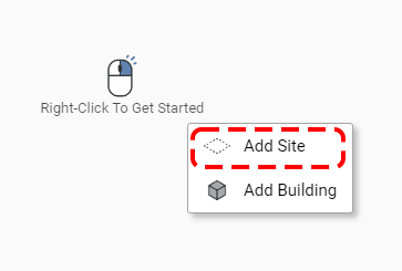
1. Right-click on the 3D view window in Planary and choose ‘Add Site’ from the popup menu.
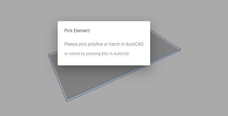
2. Return to AutoCAD and select the property line (polyline) you’ve drawn.
3. The site is linked to Planary as a ‘New Site’. You can edit the polyline/hatch in AutoCAD anytime, and the site geometry will be updated instantly.

4. Select the site in either the 3D view or the Project Tree to rename it using the Properties window.
You can also assign the site to a layer and adjust its height, which is helpful when integrating a topography layer into your project.
To learn how to add a topography layer, see the Maps article.

Add a Building
The following step involves creating a building and building parts, such as a podium and a tower.
1. Go to the Planary 3D view, right-click on the site and select ‘Add Building’.
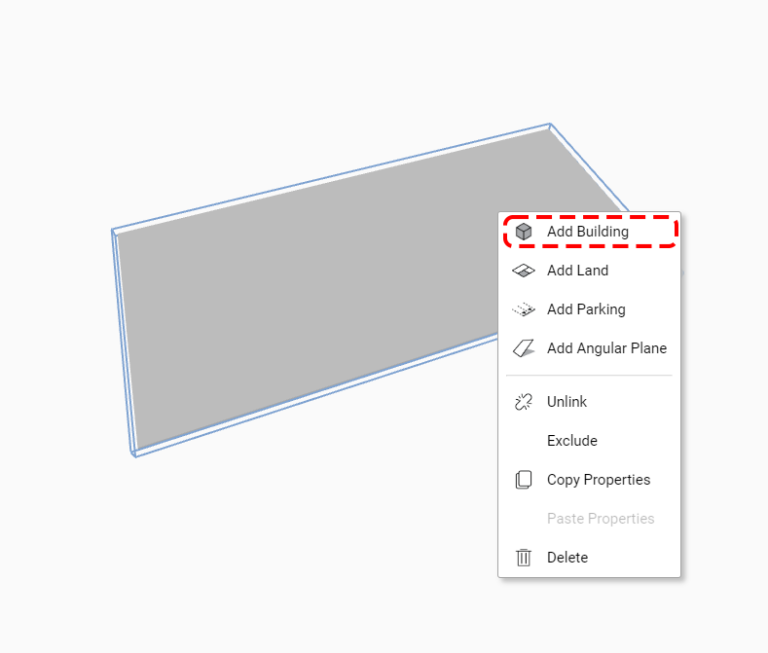
2. Pick the polyline from AutoCAD and create the first building part. Note that multiple buildings can be added to the site.
Important: Buildings that are not associated to a site can still be added to the project. To do this, right-click anywhere in the 3D view and select ‘Add Building’. Analytics for such buildings will not include site-related data, like Floor Space Index (FSI) and Building Coverage Ratio (BCR). To learn more, visit the Project Metrics article.
Building Properties
The Properties panel allows you to define key attributes for selected building parts in your project:
General:
- Building Name: Set a custom name for the building.
- Site: Change the associated site from the dropdown list.
Metrics:
- Number of Floors: Specify the number of floors for the building part.
- Floor Height: Enter the floor-to-floor height.
- Program: Assign a specific use or function to the building part.
Underground: Change the building part to below ground, typically used for underground parking. This option is only available when the building part is positioned directly on the site (at ground level).
Other:
- Layer: Assign the building part to a specific layer for organization or visibility control.
- Building Base Offset: Set the vertical offset of the building base from the ground.
- Excel Section: Define the building part to a specific section in your Excel report, if applicable.

Add an Additional Program
To add multiple programs to a building part:
1. Click the + icon.

2. Select the additional program and specify the percentage of the building part’s area to allocate to the selected program.

Customize Floors
To assign distinct heights, set programs, and rename specific floors, follow these steps:
1. Click on the adjustment icon next to the floor height.

2. Choose a floor to customize from the menu, then specify its programs, height and name.

3. An adjustment icon turning blue indicates that floor customization is applied.

ProTip: Create a Mezzanine
Exclude a percentage of the floor area by leaving a program unassigned.

Add Building Parts
To add another building part, either stacked above the previous one or placed on the same level, follow these steps:
Stacking a Building Part Above:
1. Right-click on the existing building part in the Planary 3D view and select ‘Add Building Part Above’.

2. In AutoCAD, pick the polyline/hatch that corresponds to the new building part you wish to add. This action stacks the new building part directly above the existing one.

To Add a Building Part on the Same Level:
1. Right-click on the existing building part in the Planary 3D view and select ‘Add Building on Level.’
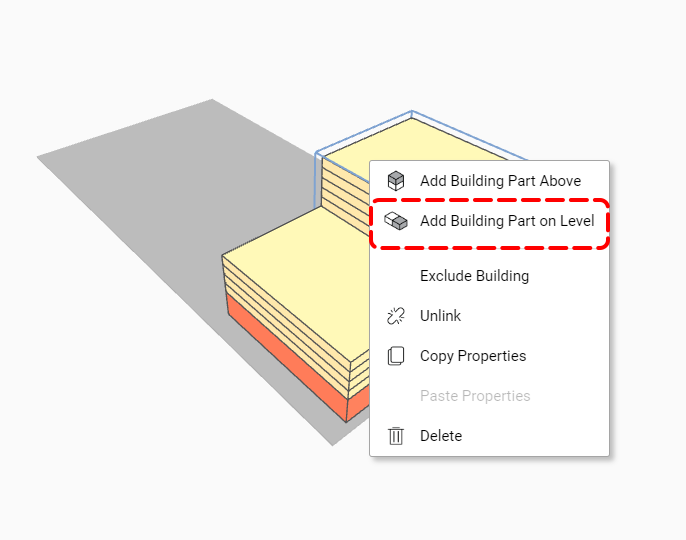
2. In AutoCAD, pick the polyline/hatch that corresponds to the new building part you wish to add. This places it on the same level as the existing part without stacking.

To Add a Building Part Below:
1. Right-click on the existing building part in the Planary 3D view and select ‘Add Building Part Below.’
Note: You can only add a building part below another part that is positioned at ground level.

2. In AutoCAD, select the polyline or hatch that corresponds to the new building part you want to add.
It will be placed below the existing part and automatically flipped to be underground — the Underground checkbox in the Properties panel will be checked.

Excluding Buildings and Sites
Excluding a building or site removes it from analytics and will not be included when exporting data and massing.
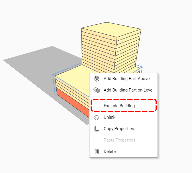
Exclude a Building:
Right-click on any part of the building you wish to exclude and select ‘Exclude Building’ from the menu. The excluded building will be displayed with transparency, indicating it is no longer part of the active analysis.
To adjust how excluded buildings appear, refer to the Project Preferences article for more details.
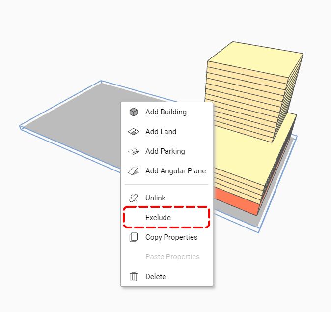
Exclude a Site:
Right-click on the site you wish to exclude, and choose ‘Exclude’ from the context menu. The site, along with its associated buildings, will be excluded and displayed with transparency.
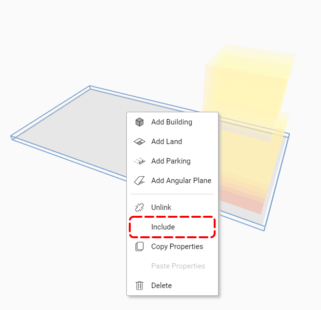
Include Site and building:
To Include a site or a building, Right-click on the element you wish to include and select ‘Include’ from the menu.
Unlink and Delete
In Planary, you have the option to unlink and relink elements to their associated polyline or hatches.
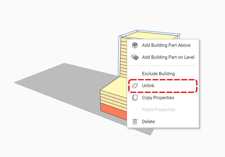
To unlink elements in Planary, right-click on the element and select ‘Unlink’ from the menu. This action detaches the element from its associated polyline/hatch.
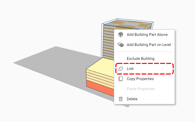
To link elements in AutoCAD, right-click on the element and select ‘Link’ from the menu.
Select the polyline or hatch from the AutoCAD you wish to link to.
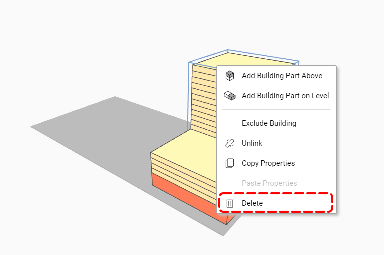
To delete an element, right-click on the element and select ‘Delete’ from the menu. This action removes the element from Planary.
Copy/Paste Properties
In Planary, you can copy and paste element properties, such as height, number of floors, and programs.
To do so:
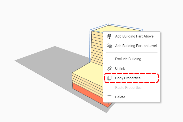
1. Right-click on the element and select ‘Copy Properties’ to copy its properties.
2. Right-click on the target element and select ‘Paste Properties’ to apply the copied properties.
Undo/Redo
You can undo or redo your actions at any time using the following methods:
- Press CTRL + Z to undo and CTRL + Y to redo.
- Alternatively, go to Edit → Undo/Redo.

Land Use
In Planary, you have the option to create lands and land use during site planning. This feature is beneficial for identifying open space programs, such as public open spaces, hardscapes/softscapes, parks, and parking lots. These areas can be customized and integrated into the overall analytics.
Create a Land Use:
1. Right-click on the site in Planary and choose ‘Add Land’.
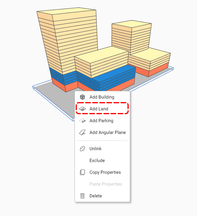
2. Pick a polyline/hatch from the AutoCAD.

3. In the properties window, you can rename the element, assign a specific use and adjust the thickness.

Add 3D Angular Plane
To add angular plan to the project:
1. Draw a line for the angular plane’s base.

2. Right-click the site, and press ‘Add Angular Plane’ from the menu. Pick the line from the AutoCAD.
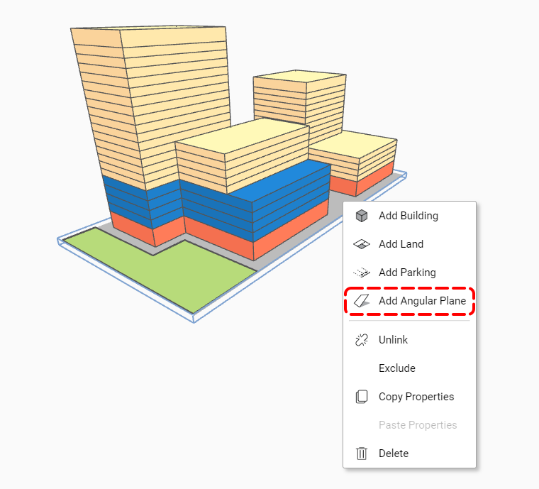
3. Under properties, you can change parameters such as name, surface thickness, length, angle, and offset from the ground.

We’ve just created a basic study with one building in Planary using polylines.
Continue to the next article to understand how to read the analysis and statistics of your study.